Other units are available on request — please inquire. For diagrams of a specific buzzer, click on “pin” or “lead” under Terminals.
| APCI Catalog No. |
Product Description |
Housing Diameter (mm) |
Dimensions Height^ (mm) |
Minimum Sound Pressure Level (dB) |
Resonance Frequency (kHz) |
Operating Voltage (VDC) |
Max. Rated Current (mA) |
Terminals | |
| 30-1275 | KPI-1410 | 13.8 | 7.5 | 85* | 4.0±0.5 | 3-16 | 7xx | pin | Spec Sheet |
| 30-1280 | KPI-2210L | 22^^ | 10.5 | 85** | 4.5±0.5 | 3~30 | 15xx | lead | Spec Sheet |
| 30-1285 | KPI-2610 | 23 | 9.8 | 85** | 3.5±0.5 | 3~24 | 10xx | pin | Spec Sheet |
| 30-1255 | KPT-1410 | 14 | 6.5 | 80*** | 4.0A±0.5 | 30 Vp-px | 3xx | pin | Spec Sheet |
| Custom | Custom |
Values to be Determined by Customer and APC International
|
|||||||
In simplest terms, a piezo buzzer is a type of electronic device that’s used to produce a tone, alarm or sound. It’s lightweight with a simple construction, and it’s typically a low-cost product. Yet at the same time, depending on the piezo ceramic buzzer specifications, it’s also reliable and can be constructed in a wide range of sizes that work across varying frequencies to produce different sound outputs.
For instance, at APC International, Ltd., we offer piezo buzzers without signal generators, self-oscillating buzzers that have signal generators and even multi-tone sound generators — often used in alarms and sirens. Regardless of the model you choose, our piezo buzzers offer high sound outputs. Plus, since they can be mounted on circuit boards, they’re highly useful in a wide range of applications and assemblies.
Despite different construction methods that affect the cost of piezo buzzers, all of our prices are highly competitive. In addition, thanks to our state-of-the-art production facility, our delivery times are some of the fastest in the industry.
The use of the piezo ceramic buzzer was discovered thanks to an inversion of the piezoelectricity principle that was discovered by Jacques and Pierre Curie back in 1880. They found that electricity could be generated when a mechanical pressure was applied to particular materials — and the inverse was true as well.
So when certain piezoelectric materials are subjected to an alternating field of electricity, the piezo buzzer element — often a manmade piezoceramic material — stretches and compresses in sequence with the frequency of the current. As a result, it produces an audible sound.
Unlike magnetic buzzers that have a narrow operating voltage of somewhere between one and 16 volts, piezo buzzers can typically operate anywhere between three and 250 volts. In addition, magnetic buzzers have a higher power consumption of 30 to 100 milliamperes, while piezo buzzers normally consume less than 30 milliamperes — even at higher rate frequencies. And although piezo buzzers require a larger footprint than magnetic buzzers, they produce a higher sound pressure level.
Thanks to both the reliability and flexibility of piezoelectric vibration plates to produce audible signals — ranging from monotone buzzes and alarms to multi-tones and melodies — their applications in small, high-density assemblies are wide-ranging. What’s more: Their low power consumption makes them ideal for many battery-operated devices.
With such characteristics, piezo buzzers are regularly used in alarms, warning devices and automobile alerts. In addition, since they can produce a wide range of audible signals, they’re also used in pest deterrent devices. And in the consumer electronics field, some of their most popular applications include sound generators in computers, telephones, toys and games — to name just a few.
Simple, compact, and reliable, piezoelectric audible sound transducers—also called tone generators, or buzzers—can deliver a high sound output from a small (milliwatt) energy input. Emitted sounds range from soft hums to strident alarms. These devices are well suited for use in portable, battery powered equipment, and are employed in a wide variety of products, including timers, smoke alarms, games, telephone ringers, metal detectors, watches, automobile alarms, and many others.
The working component in most audible sound transducers is a thin disk of piezoelectric ceramic bonded to a similarly thin metal diaphragm. When a voltage is applied to the ceramic disk, the disk deforms, causing the metal diaphragm to bend. When a recurring voltage is applied the ceramic / metal bending element vibrates at the frequency of the applied voltage, and produces an audible sound. If the mechanical resonance frequency of the ceramic / metal element and the frequency of the applied electrical signal are matched, the amplitude of the vibrations will be greatest, and sound output will be maximum. (The resonance frequency of the ceramic element alone is too high to produce audible sound, hence the need for the metal diaphragm.)
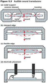
The construction of a piezo ceramic buzzer greatly affects the level of the sound it emits — and the cost of the device. Nodal support mounting minimizes mechanical restriction on the movement of the sound-producing mechanism, so the amplitude of the vibrations is highest. On the other hand, signal originating from beyond the nodal ring will be in antiphase with signal from the central part of the element, and can reduce the sound output. To prevent this interference, the housing must absorb all output from the periphery of the element.

In flexible edge mounting, the flexing element is restrained in a pliant material, such as a rubber. This ensures excellent signal characteristics, at a resonance frequency half that for the same element in one of the other mounting alternatives. Again, however, careful construction of the device is critical to effective performance.
The resonance frequency, fr, for the ceramic disk / metal diaphragm bending element in an audible sound transducer can be determined from Equation 5.1:
Equation 5.1
ƒr=(0.412h / rdisk2) (√(Y / ρ[1-σE2]))
where
h=height (thickness of ceramic / metal bending equipment
rdisk= radius of ceramic / metal binding element
Y= Young;s modulus*
ρ=density of ceramic material (kg/m3
σE= Poisson’s ratio**
* ratio of stress applied to strained developed; Y= (force / area of element) / (change in height of element / orginal height of element)
** compressibility; σE=sE12/ sE11 where sE= elastic compliance (transverse contraction strain / longitudinal expansion strain) in a constant field.
If the sound-producing ceramic / metal bending element is assumed to be a homogeneous unit, the resonance frequency is proportional to the overall height of the ceramic disk and metal diaphragm (h) and is inversely proportional to the square of the radius of the bending element (rdisk):
Equation 5.2
ƒ=(α)(h / rdisk2)
where
α= 0.412 (√(Y / ρ[1-σE2]))
For any perovskite piezoelectric ceramic σE is approximately 0.3 (1), therefore α becomes: 0.412 (√(Y / 0.91ρ))
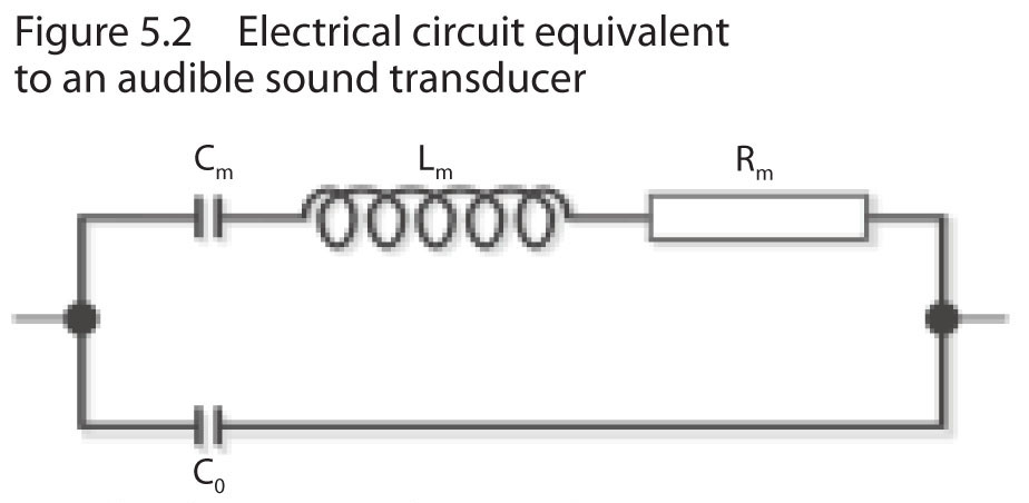
Figure 5.2 shows an electrical circuit equivalent to an audible sound transducer. Rm, Lm, and Cm express the mechanical resonance of the sound-producing mechanism, fr :

Co = (capacitance of ceramic element below resonance frequency) – (Cm)
Cm = capacitance of mechanical circuit
Lm = inductance of mechanical circuit
Rm = resistance caused by mechanical losses
Equation 5.3
ƒ= 1 /(2π) (√ LmCm)
where
Lm= inductance of mechanical circuit
Cm= capacitance of mechanical circuit
The manner in which a piezo buzzer is constructed affects the resonance frequency and the level of sound the device emits, the extent of unit-to-unit variation in production, the conditions under which the device can be used, and the cost of the device. Figure 5.3 shows three alternative possibilities for buzzer design. In the nodal support mounting, the flexing element is clamped into the housing around the nodal ring – a ring approximately 2/3 the distance from the center of the element to the periphery of the element, around which there is no vibration when the mounted element is stimulated. This mounting option minimizes the mechanical restriction on the movement of the sound-producing mechanism, so the amplitude of the vibrations is highest. On the other hand, signal originating from the outer part of the element, beyond the nodal ring, will be in antiphase with signal from the central part of the element, potentially causing interference and reducing the sound output. To prevent interference, the housing in which the buzzer is mounted must absorb all output from the outer part of the element. Assuming the potential interference is nullified, nodal support mounting is the best choice for self-driven, high output applications.
In the clamped edge mounting, the flexing element is clamped to the housing around its periphery. This allows the entire surface of the element, except a narrow band around the peconditions, the vibration frequency for a flexing element in a clamped-edge mounting will be approximately the same as would be exhibited by the central part of the flexing element if the element were mounted in a nodal support mounting. Relative to nodal support construction, however, greater interaction between the sound producing element and the housing reduces the mechanical quality factor of the element and, consequently, the amplitude of the vibrations is lower. Furthermore, unit to unit variations in clamping can affect the uniformity of product performance, and a more substantial housing generally is needed to retain the element.
Flexible edge mounting is similar to clamped edge mounting, except that in the flexible edge design, the flexing element is not rigidly clamped in the housing, but instead is restrained in a flexible material, such as a rubber. The pliant restraint allows angular movements at the periphery of the flexing element, and this ensures excellent signal characteristics. The mechanical resonance frequency for a flexing element in a flexible edge mounting is half that for the same element in a nodal support mounting or a clamped edge mounting. Similar to the constraints on clamped edge mounting, however, careful construction of the device is critical to its effective performance. Flexible edge mounting is used to the most advantage by incorporating it into a system driven by external drive circuitry.
A fourth alternative—supporting the disk at its center—is possible, but the design is difficult to execute, and sound pressures will be lowest with this option.


Fill out our contact form, request a quote, or call us at 570.273.0014 for more information on piezo buzzers.