When exposed to an AC electric field, a piezoelectric ceramic element changes dimensions cyclically, at the cycling frequency of the field. Resonance frequency is the frequency at which the ceramic element vibrates most readily, and most efficiently converts the electrical energy input into mechanical energy.
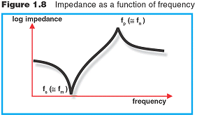
The pattern of an element’s responses is depicted in Figure 1.8. As the frequency of cycling is increased, the element’s oscillations first approach a frequency at which impedance is minimum (maximum admittance). This minimum impedance frequency, fm , approximates the series resonance frequency, fs , the frequency at which impedance in an electrical circuit describing the element is zero, if resistance caused by mechanical losses is ignored. The minimum impedance frequency also is the resonance frequency, fr. The composition of the ceramic material and the shape and volume of the element determine the resonance frequency — generally, a thicker element has a lower resonance frequency than a thinner element of the same shape.
As the cycling frequency is further increased, impedance increases to a maximum (minimum admittance). The maximum impedance frequency, fn , approximates the parallel resonance frequency, fp , the frequency at which parallel resistance in the equivalent electrical circuit is infinite if resistance caused by mechanical losses is ignored. The maximum impedance frequency also is the anti-resonance frequency, fa. Maximum response from the element will be at a point between fm and fn.
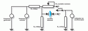
Values for minimum impedance frequency, fm , and maximum impedance frequency, fn , can be determined by measurement. Figure 1.10 shows a system designed to ascertain these values, and summarizes the procedure.

A ceramic element’s oscillations first approach the minimum impedance frequency (fm ) / resonance frequency (fr ), at which the element vibrates most readily, and most efficiently converts electrical energy into mechanical energy. As cycling frequency is further increased, impedance increases to the maximum impedance frequency (fn ) / anti-resonance frequency (fa ).
Figure 1.10. System for Determining Minimum Impedance (Resonance Frequency) and Maximum Impedance (Anti-Resonance Frequency) of a Piezoelectric Ceramic Element

fm and fn can be used to calculate the electromechanical coupling factor, k. k depends on the mode of vibration and the shape of the ceramic element. The relationships between k and fm and fn for a ceramic plate, a disc (surface dimensions large, relative to thickness), or a rod are:
![]()
* electric field parallel to direction of polarization,
induced strain perpendicular to direction of polarization
![]()
** electric field parallel to direction of polarization,
induced strain in same direction
![]()
*** electric field parallel to direction of polarization,
induced strain in same direction
Determining Resonance Frequency
Traditional Piezo Stack Actuators for Ultrasonic Transduction Applications
Principals of Piezoelectric Energy Harvesting

For much more information about piezoelectric ceramics and their uses, order our book:


Have questions about APC International’s piezo products? Contact us or call us at (570)726-6961 to learn more information.