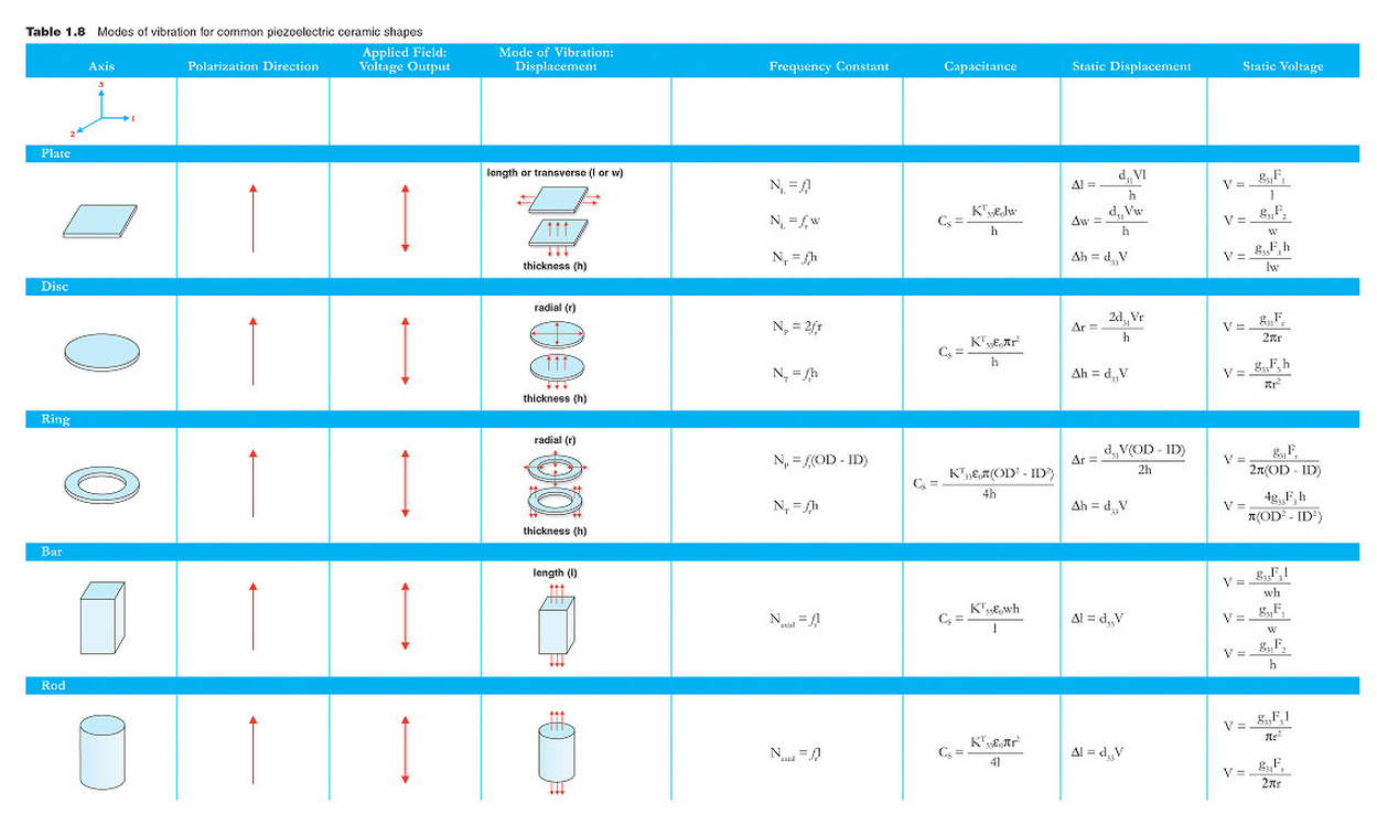
Click on this table to view in larger format or click button to print. (Table 1.8A)
Click on this table to view in larger format or click button to print. (Table 1.8B)
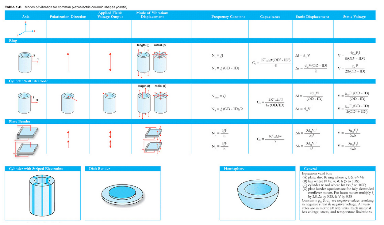
Cscapacitance
d piezoelectric charge constant (C / N)
E0 permittivity of free space (8.85 x 10⁻¹² farad / m)
fr resonance frequency (minimum impedance frequency) (Hz)
F force
g piezoelectric voltage constant (Vm / N)
h height (thickness) of ceramic element (m)
ID inside diameter of ceramic element (m)
KT relative dielectric constant (constant stress)
I length of ceramic element (m)
N frequency constant (Hz-m)
OD outside diameter of ceramic element (m)
r radius of ceramic element (m)
V voltage
w width of ceramic element (m)
For much more information about piezoelectric ceramics and their uses, order our book:

Have questions about APC International’s piezo products? Contact us or call us at (570) 726-6961 to learn more information.